In this guide
Load should always be introduced vertically into the direction of measurement to avoid errors from misalignment, off-center or torsional moments, and transverse and lateral forces. LAUMAS states that maximum static load (yield strength) is normally between 120% and 150% of full scale; exceeding it permanently deforms and damages the load cell. OIML R 60 mandatory additional information (accompanying document or on-cell marking) must include other pertinent conditions to obtain specified performance (for example cable details, mounting torque).
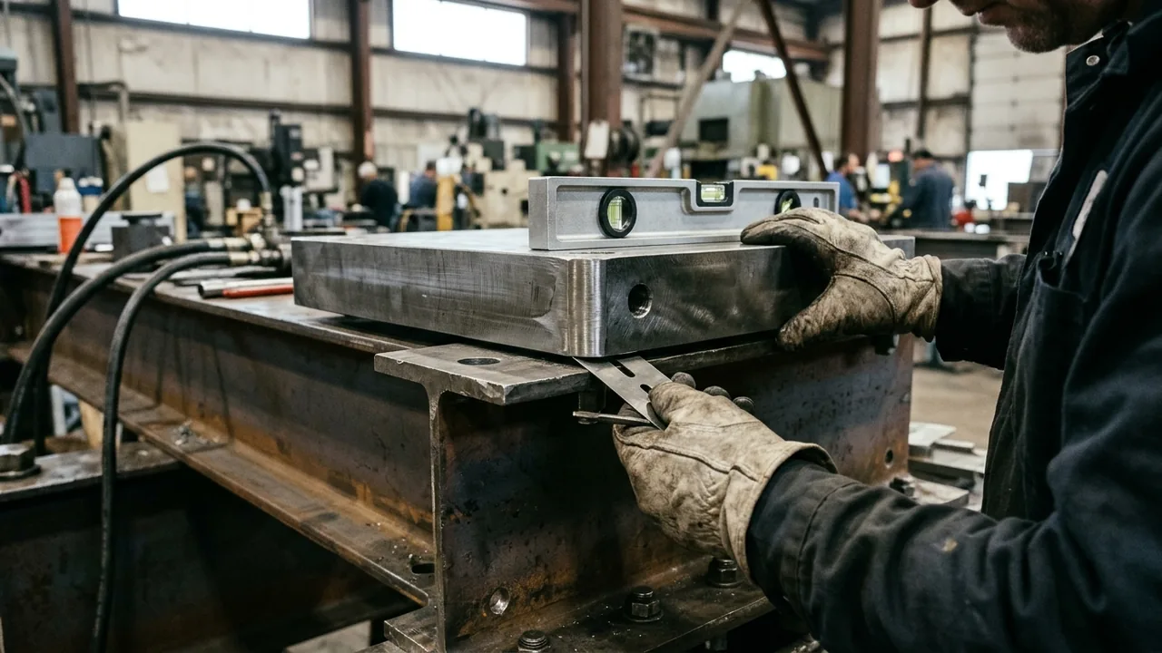
Inspect baseplate flatness, leveling, and support contact before bolting
Deflecting floors can cause short wave vibrations that lead to inaccuracy, so weak foundations or deflection should be reinforced. As a general rule of thumb for high accuracy, load cell or weigh module leveling must be within 0.5° in any direction, equal to a slope of 1mm (1/32inch) per 100mm (4inches). VPG Force Sensors states that misalignment greater than 2-3 degrees from perpendicular to the mounting surfaces introduces side-load errors, and recommends rechecking calibration accuracy after the first 24 hours of operation to account for settling.
| Mounting Parameter | Grounded Requirement and Documented Effect |
|---|---|
| Parallel support alignment | METTLER TOLEDO single-ended beam load cells (0743, 0745A, MTB, SLB215, SLB415, SLB515) require adequate rigid support that is level parallel within <3mm / 1/8 inch. |
| Support deflection limit | For METTLER TOLEDO single-ended beam load cells, rigid base plates must keep uniform deflection of the top and bottom weigh module supports to less than 0.5°. |
| Beam axis and dead-end mounting | For METTLER TOLEDO single-ended beam load cells, the longitudinal axis is positioned horizontally and the dead end of the load cell is screwed to a horizontal base plate. |
| Multi-cell load sharing | Massload Technologies notes that in structures using four or more load cells, weight distribution is rarely even and typically 85 to 90 percent of the load is carried by just three supports. |
| Unweighted support shimming | In a structure with four-point support using LAUMAS PV or PVZ mounting kits, if one point does not touch the upper part of the mounting kit, a shim must be inserted before fixing the bolts. |
| Mating surface hardness and flatness | Morehouse documents that changing top pad material or hardness can shift load cell output by up to approximately 0.3 %, while a non-flat adapter or base triples repeatability errors and increases rotational error by approximately 5×. |
Prevent torsional twist through dead-end orientation and fastener torque
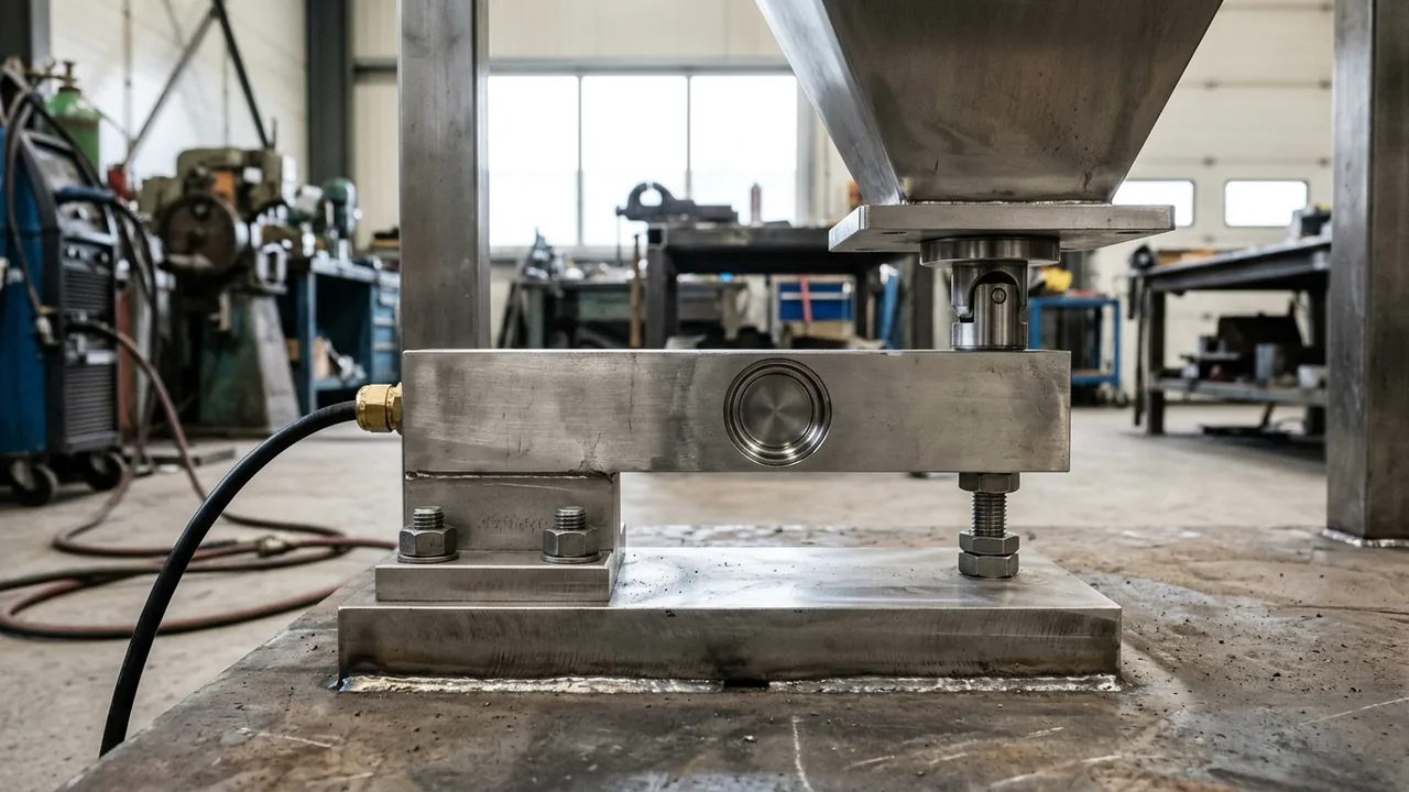
Torsional loading occurs when a side force twists a load cell due to structural deflection, system dynamics, thermal movement, or mounting hardware misalignment. On METTLER TOLEDO SLS410 and SLS510 tension S-beam load cells, the cable must exit from the dead side of the load cell; otherwise the cable acts as a live-to-dead bridge and causes inaccuracies. Morehouse documents that rigging misalignment of less than 1/8 inch on a 10,000 lbf S-beam load cell produced a 0.752 % error and increased expanded uncertainty approximately 9-fold (from roughly 10 lbf to 90 lbf). Morehouse documents that comparing full thread-through loading to flat-on-flat loading on an S-beam load cell in compression produced a maximum output difference of 0.369 %, and almost 0.03 % error when loading flat on the bottom while threading on top.
On shear-web load cells, leaving one or two alignment-plug threads exposed below the load cell transfers load through the internal threads rather than the base and adds approximately 0.012 % calibration error; the plug should be threaded flush to the bottom plus one additional turn in. In a Morehouse calibration example on a 60,000 lbf bolted load cell, changing bolting torque from 25 lbf ft to 45 lbf ft produced about a 0.7 percent output difference, and missing or unevenly torqued bolts produce errors three times expected performance. LAUMAS FTK load cells are made of AISI 4340 nickel plated steel with bending-beam capacities from 75 kg to 300 kg and shear-beam capacities from 500 kg to 5000 kg.

| Load Cell or Kit Series | Fastener Grade, Thread Size, and Tightening Torque |
|---|---|
| Compact single-ended beam | METTLER TOLEDO MTB load cells with 5-300 kg (11-661 lb) capacity specify Grade 8.8 (USA Grade 5) M8x1.25 (5/16-18 UNC) bolts torqued to 15 Nm (11 ft lb). |
| Higher-capacity bellows beam | METTLER TOLEDO MTB load cells with 500 kg (1102 lb) capacity specify Grade 8.8 (USA Grade 5) M10x1.5 (3/8-16 UNC) bolts torqued to 20 Nm (14.5 ft lb). |
| Medium shear beam | METTLER TOLEDO 0745A load cells with 110-2200 kg (250-5000 lb) capacity specify Grade 10.9 (USA Grade 8) M12 (1/2-13 UNC) bolts torqued to 98 Nm (70 ft lb). |
| Heavy shear beam | METTLER TOLEDO 0745A load cells with 4400 kg (10000 lb) capacity specify Grade 10.9 (USA Grade 8) M18x1.5 (3/4-10 UNC) bolts. |
| Hermetic and stainless shear beams | METTLER TOLEDO SLB215 and SLB415 load cells with M12 (1/2-13 UNC) Grade 10.9 (USA Grade 8) bolts are listed above the SLB515 row, which specifies 98 Nm (70 ft lb) for M12. |
| Bench single-point cell | METTLER TOLEDO SLP845 single-point load cells specify Grade A4-70 M6/1 bolts with 10 mm (0.4 in) engaged length and 10 Nm (7.4 ft lb) torque, with a 400x500 mm (15.7x19.6 in) maximum platter size on the 50-200 kg rows. |
| Nickel-plated steel beam | For LAUMAS FTK load cell fixing screws, tightening torque is 50 Nm (class 6.8) or 79 Nm (class 8.8) for M12 screws, and 290 Nm (class 6.8) or 400 Nm (class 8.8) for M20 screws. |
| Stainless steel shear beam | LAUMAS FTP load cells are made of AISI 420 stainless steel and include M24 fixing screws torqued to 500 Nm (class 6.8) or 690 Nm (class 8.8) in addition to M12 (50 Nm / 79 Nm) and M20 (290 Nm / 400 Nm). |
| Self-centering weigh module | On LAUMAS PV and PVZ mounting kits, the lock must touch under the load cell during transport and installation and be moved away afterward, and load cell fixing screws are torqued to 50 Nm for PV and 79 Nm for PVZ. |
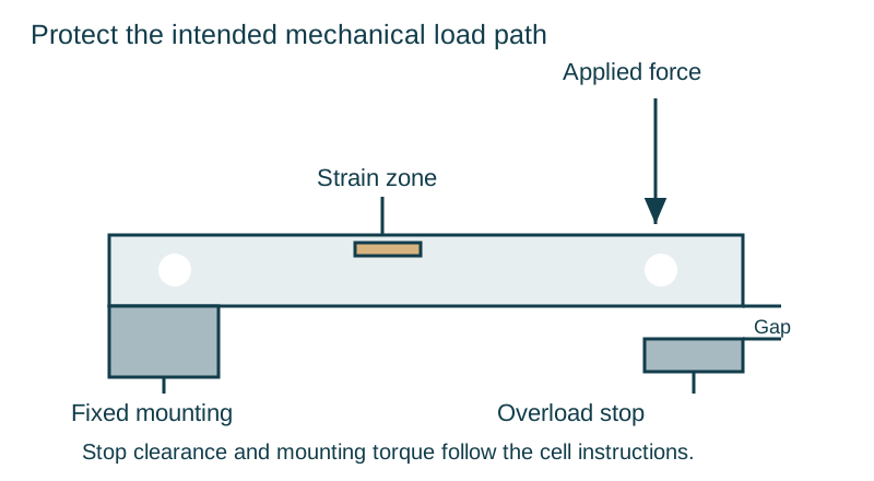
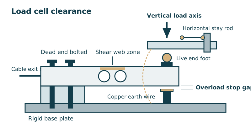
Set vertical overload stop gaps to nominal deflection and load limits
Maximum capacity (Emax) is the largest value of a quantity expressed in units of mass that may be applied to a load cell. Minimum dead load (Emin) is the smallest value of a quantity expressed in mass units that may be applied to a load cell. Safe load limit (Elim) is the maximum load that can be applied without producing a permanent shift in the performance characteristics beyond those specified. For static weighing safety, LAUMAS advises using load cells at a maximum of 70-80% of nominal capacity assuming uniform load distribution across the weighed structure.
LAUMAS states that standard load cell breaking load is usually between 250% and 300% of full scale, while deflection at nominal load is between 0,2 mm and 1 mm (0,5 mm in an AZL load cell). HITEC Sensor Developments states that minor excursions into the severe overload range are normally associated with unexplained calibration changes or zero shifts, and, in general, shock protection is only afforded by those designs where the load cell base is directly connected to the machine frame or in some way is prevented from accelerating and producing damaging reaction forces.
| Load Cell Series | Safe Overload, Ultimate Overload, and Nominal Deflection |
|---|---|
| Alloy steel bending and shear beam | LAUMAS FTK load cells specify 150% safe overload, 250% ultimate overload, and 0.6 mm deflection at nominal load. |
| Stainless steel bending and shear beam | LAUMAS FTP load cells specify 150% safe overload, 200% ultimate overload, and 0.4 mm deflection at nominal load. |
| Low-profile compression disk | LAUMAS CBL low-profile compression load cells are made of 17-4 PH stainless steel and specify 150% safe overload, 300% ultimate overload, and 0.4 mm deflection at nominal load. |
METTLER TOLEDO single-point load cells require spacer plates to create deflection clearance, except MT1041, SSH (50-500 kg) and IL (1000 kg) which have a built-in spacer (1mm on MT1041). For METTLER TOLEDO single-point load cells, set the overload stop by adding scale capacity to the center, tightening the protection screw until weight changes on the terminal, reversing it slightly, locking the nut, and testing corner performance. For METTLER TOLEDO SLS410 and SLS510 tension load cells, install a secondary safety support system (chain or rods) and leave clearance between the lower support bracket and the safety-rod washer.
Isolate side loads, pipe forces, and welding currents with mounting hardware
Side and end loading occur when horizontal forces from thermal expansion and contraction, misalignment, or dynamic vessel movement are applied to a load cell, affecting scale linearity and hysteresis. LAUMAS PV (AISI 304 stainless steel) and PVZ (galvanized steel) mounting kits have an up to 2000 kg application range for FTK, FTKL, FTP, FT-P, and FTZ load cells with lateral-force and anti-tilt constraint. LAUMAS V10000 and V10275 mounting kits have an up to 15000 kg application range for CBL, CBX, and CX compression load cells, with AISI 304 laminas against lateral forces and two threaded rods with self-locking nuts for anti-tilt constraint. LAUMAS TENDITORE300 is a galvanized steel turnbuckle with dual ball-and-socket for horizontal mounting-kit constraints up to 100000 kg, with a 2500 kg working load and 10000 kg ultimate overload.
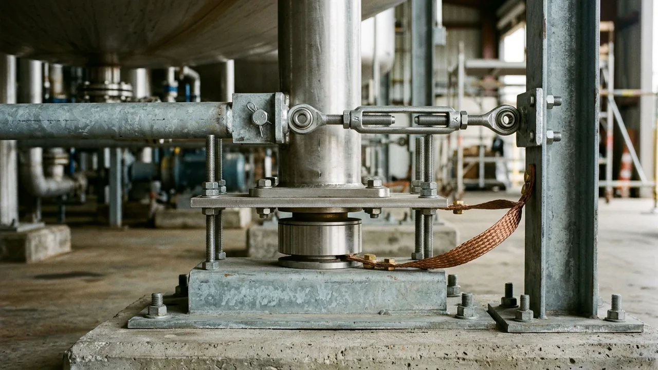
When installing LAUMAS V10000 / V10275 mounting kits, insert a piece of pipe 1-2 mm higher than the load cell during welding and structural assembly, then install the load cell and turn the anti-tilt nuts to a distance of 1 mm from the plate. Do not pass welding current through load cells, and never weld closer than 1.2 meter (4 feet) to any load cell without removing the load cell. LAUMAS instructs connecting each load cell’s upper support plate to its lower support plate with a copper wire and connecting all lower plates to a single earthing system. When hard pipes connect to a weighed structure, LAUMAS recommends placing the pipe support or anchor bracket at a distance of at least 40 times the pipe diameter from the weighed structure.
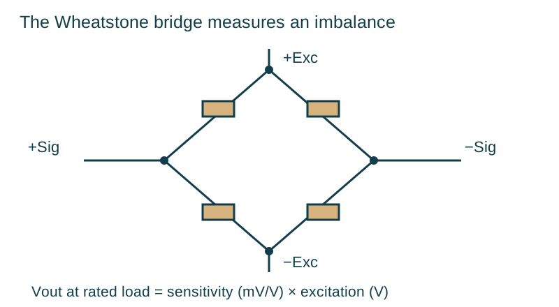
In LAUMAS’s unloaded load cell check with 5 VDC ±3% excitation, the response signal between the positive and negative signal wires must be between 0 and ±0.5 mV. In LAUMAS’s load cell resistance check, the insulation resistance between the shield and any cell wire and between any cell wire and the load cell body must be higher than 20 MΩ. Continue with the Wheatstone bridge and sense wiring guide or review packaging load cell fundamentals.
Record the mechanical setup before replacing parts
Prepare these mechanical details before ordering mounting hardware or replacement sensors:
- The mechanical installation drawing showing baseplate thickness, pipe connections, and dead-end orientation.
- The cell capacity, empty structure weight, and live loading profile.
- Whether horizontal stay rods, self-centering mounts, and vertical overload stops are present and what clearance gap is set.
Continue with the load cells and controls collection.
Sources
- International Organization of Legal Metrology, Metrological Regulation for Load Cells
- METTLER TOLEDO, Load Cell and Accessories Installation Manual
- LAUMAS Elettronica, Load Cell Technical Features and Installation Data Sheets
- Morehouse Instrument Company, Bad Load Cell Setup
- VPG Force Sensors, Weigh Modules and Load Cell Mounts
- HITEC Sensor Developments, Overload Protection in Electronic Weighing Systems
- Massload Technologies, Load Cell Mounting Methods and Their Effect on Performance