In this guide
The strain gauge and load cell work together through a mechanical and electrical conversion: force deforms the elastic element, gauge resistance changes, and the Wheatstone bridge produces a differential signal. Understanding that chain helps distinguish low sensitivity, cable voltage drop and a mechanically restricted weighing assembly.
Trace the bridge before tracing wire colours
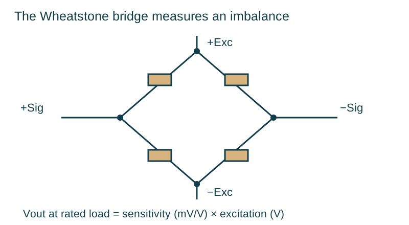
A Wheatstone bridge has four resistive arms. Excitation is applied across one diagonal, and the instrument measures the voltage across the other. With suitable gauge placement, tension and compression change the arm resistances so the differential output responds to load. The wiring diagram determines polarity and terminal assignment.
For two simple voltage-divider branches, the differential output can be written as Vout = Vexc × [R₂/(R₁+R₂) − R₄/(R₃+R₄)], with the sign set by the chosen signal terminals. Equal ratios balance the bridge. Real load cells include compensation and trimming appropriate to their design, so diagnose them against the supplied circuit and specification.
Use mV/V as a sensitivity, not a weight
LAUMAS defines rated output as the millivolt signal at maximum load divided by the excitation voltage in volts. For a specific cell, rated-load output (mV) = rated sensitivity (mV/V) × actual excitation at the cell (V). Use the data-sheet sensitivity and the voltage actually present at the bridge.
For a proportional response within the rated measuring range, the load-dependent component scales with applied load / rated capacity. The calibrated zero, dead load and the cell’s specified errors must also be considered. The mV/V value is therefore an electrical conversion factor; calibration establishes the relationship to the installed weighing system’s mass indication.
A larger excitation may produce a larger signal, but the cell and transmitter limits govern permitted excitation. Heating, supply capability and the number of connected cells also matter. Choose compatible components rather than increasing excitation to compensate for an unexplained fault.
Compare four-wire and six-wire compensation
| Connection | Conductors | What the instrument observes | Installation consequence |
|---|---|---|---|
| Four-wire | +Exc, −Exc, +Sig, −Sig | Bridge signal with excitation delivered through the cable | Preserve the specified cable arrangement and account for lead drop |
| Six-wire | The four above plus +Sense and −Sense | Bridge signal and excitation measured at the cell | Compatible sensing can compensate changes in excitation lead drop |
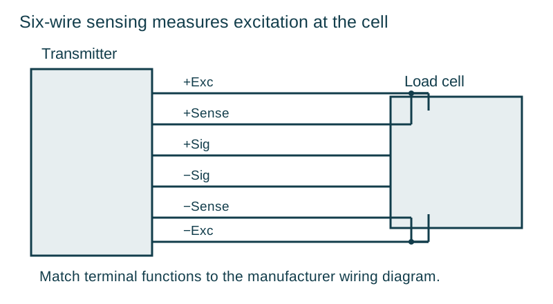
LAUMAS explains that six-wire reference leads compensate changes in cable voltage drop caused by factors such as temperature and cable length. It also states that four-wire cells are calibrated and thermally compensated with their standard cable, so that length should not be altered casually. Follow the manufacturer’s junction-box and indicator instructions when a four-wire cell joins a longer system cable.
The sense pair is not a second weight signal. It is part of the excitation-reference arrangement. When a transmitter requires sense terminals to be linked for a four-wire connection, place those links exactly where its wiring instructions specify. Do not rely on a remembered colour convention from another brand.
Protect the cell mechanically
The elastic element must move through its intended small deflection without binding. Correct load introduction, mounting surfaces and fastener procedures matter as much as cable continuity. A hose, cable or guide can apply a force that follows machine movement or temperature and looks like electronic drift.
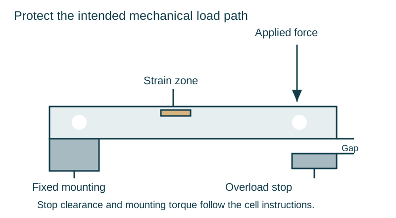
Set overload protection from the cell or machine instructions. A stop with insufficient clearance can carry normal load and distort the response. Excessive clearance may allow damaging deflection before the stop engages. Consider maintenance loads, impact and off-axis forces in the installation design, not only the package’s nominal mass.
Diagnose from force to indication
Begin with the unloaded assembly, mechanical freedom and visible cable condition. Record zero, response to a suitable reference load and return to zero. Where supported, compare the transmitter’s raw mV/V indication with its scaled weight value. This separates a changing sensor signal from a scaling or recipe problem.
Electrical resistance and insulation checks require the specified isolation and test method. Protect connected electronics from inappropriate test voltages. If the cell shows persistent zero shift after a known overload, document the event and seek qualified assessment rather than repeatedly zeroing it away.
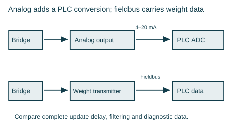
OIML R 60 provides the metrological framework for load cells. Apply its component requirements together with the complete instrument’s design and verification obligations. Continue to the amplifier and fieldbus guide when the bridge signal is sound but the control response remains slow or noisy.
Continue with the load cells and controls collection.