In this guide
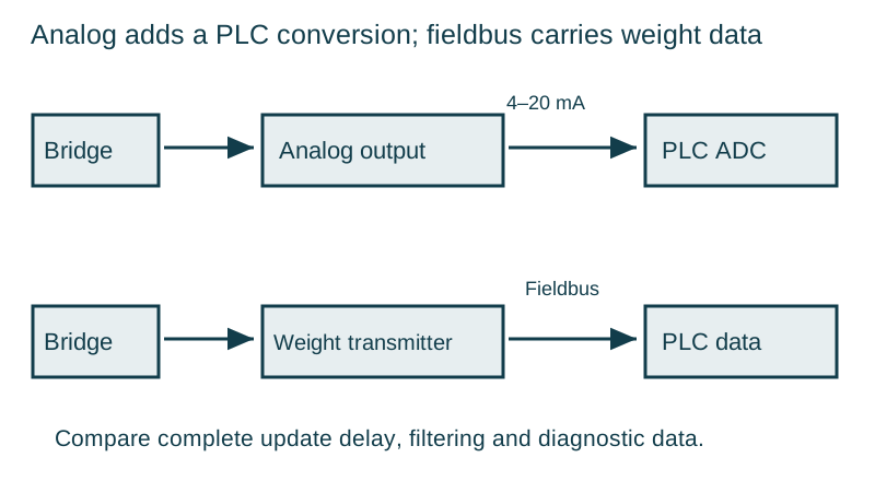
A strain-gauge load cell converts force into a small electrical signal. The elastic element deforms under load; bonded gauges change resistance; a bridge circuit turns those changes into a differential voltage. The transmitter scales that voltage into a weight value. Each part of this chain can introduce a fault that appears at the same display.
Establish the mechanical load path
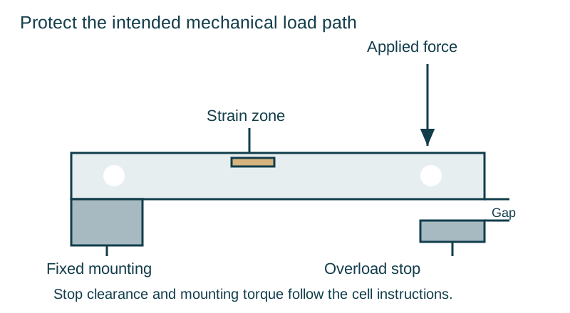
Flintec’s load-cell explanation connects applied force, elastic deformation, bonded gauges and signal conditioning. In a packaging machine, the measured assembly may be a hopper, platform or conveyor. Its load must reach the cell through the intended mounting arrangement.
Inspect contact with guards, guides, cables and hoses. Friction or a rigid connection can carry part of the load around the sensor or apply an additional force. Check overload stops and transport restraints against the equipment instructions. A stop that touches during normal weighing can make the response nonlinear; excessive clearance can reduce protection against overload.
Read the electrical specification correctly
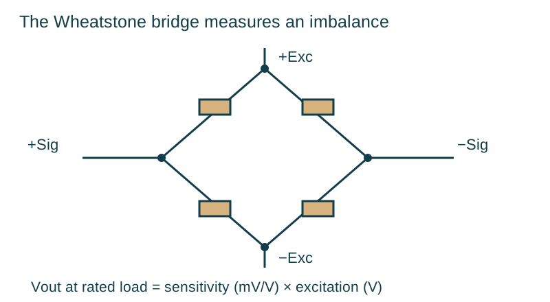
Rated output in mV/V expresses the output voltage at rated load relative to excitation voltage. For a particular cell, use its rated sensitivity and permitted excitation range. The output at rated load follows Vout = sensitivity × excitation, with mV/V multiplied by V giving mV. This is an electrical relationship, separate from the calibrated mass scale.
Bridge resistance, zero balance, insulation, temperature effects and creep describe other aspects of performance. A display with many digits does not remove those influences. LAUMAS distinguishes the compensated temperature range from the broader working range; performance claims must be read with those conditions.
| Data-sheet item | Meaning for the application | Check before selection |
|---|---|---|
| Rated capacity | Intended maximum measuring load | Dead load, live load and mechanical events |
| Rated output | Signal per excitation voltage at rated load | Transmitter input compatibility |
| Creep | Change under a sustained load over a specified period | Hold duration and stability requirement |
| Zero and span temperature effects | Response to changing temperature | Actual installation environment |
| Overload limits | Limits under stated loading conditions | Shock and protection design |
| Protection rating | Enclosure protection under defined conditions | Cleaning chemicals, temperature and installation |
Distinguish four-wire and six-wire connections
A four-wire cell carries excitation and signal pairs. A six-wire arrangement adds a sense pair that allows compatible electronics to observe excitation at the cell. LAUMAS explains that sense feedback compensates for changes in cable voltage drop. It also warns that its four-wire cells are compensated with their supplied cable length, so cable changes require particular care.
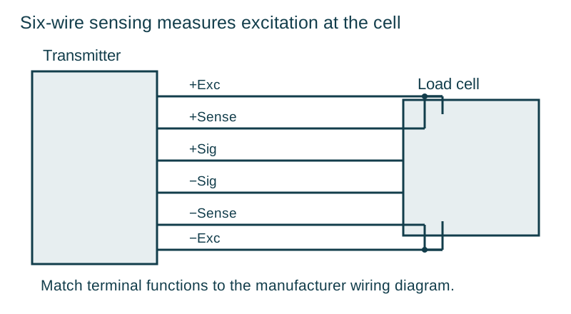
Follow terminal functions and the actual wiring drawing; colours differ between manufacturers. Keep shield and earth arrangements consistent with the instrument instructions. Route sensitive measurement wiring away from motor-power and variable-frequency-drive wiring where required by the installation design.
Diagnose in a controlled sequence
First inspect mechanical freedom and cleanliness. Then record empty zero, a reference load response and return to zero using an authorized procedure. Compare the raw signal or per-channel values where the transmitter exposes them. A changing zero with no intended load may indicate mechanical force, moisture, cable damage, temperature effects or cell damage.
Qualified personnel can check connections and resistance according to the manufacturer’s procedure with the system safely isolated. Avoid applying insulation-test voltages to connected electronics unless the manufacturer explicitly permits the test. Record the wiring configuration before disconnecting any conductor.
Read: OIML R 60 — Metrological regulation for load cells.
Keep component approval and system performance distinct
OIML R 60 addresses metrological requirements and tests for load cells. The performance of an assembled scale also depends on mounting, load distribution, electronics, software and its applicable instrument requirements. Match component characteristics and approvals to the complete design.
For the bridge equation, cable compensation and overload protection in more detail, continue with the four-wire and six-wire bridge guide.
Continue with the load cells and controls collection.