
Follow force all the way to the PLC
A weighing indication depends on the mechanical load path, the sensing principle, signal conversion and control interface. Start with mechanical freedom before diagnosing a transmitter or changing software filters.
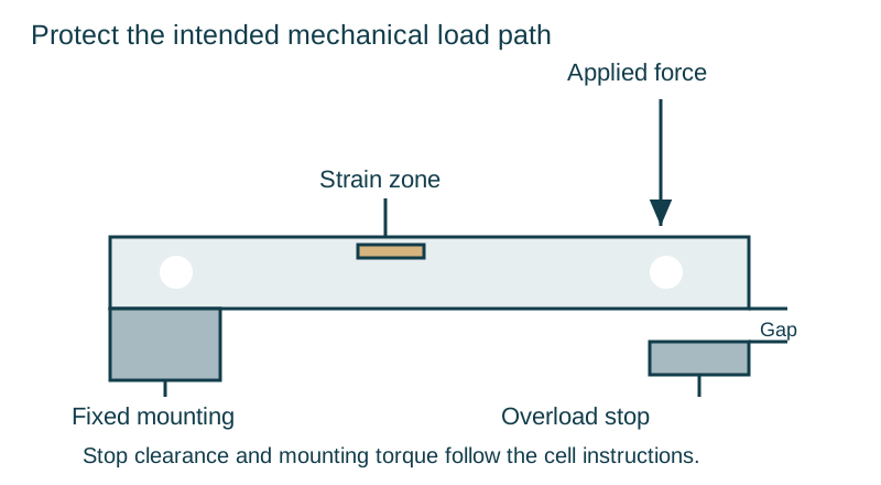
Compare sensing principles
A strain-gauge cell measures elastic deformation through a resistive bridge. An electromagnetic force-restoration system balances the applied load with an electromagnetic force and derives the measurement from that balancing action. Shimadzu explains this balancing-current principle in its guide to electromagnetic and load-cell weighing. The complete instrument still needs appropriate mounting, environmental control and dynamic verification.
Read the conversion specifications in context
Bridge sensitivity, ADC resolution, conversion frequency and displayed divisions describe different parts of the chain. Filtering and communication introduce response characteristics that matter when a PLC must stop a fast fill.
| Interface | Integration task |
|---|---|
| 4–20 mA or 0–10 V | Align conditioner output, PLC input scaling and fault detection |
| Modbus | Confirm register map, data type, scaling and update behaviour |
| CANopen or industrial Ethernet | Confirm the exact device variant, process data and watchdog response |
Build a diagnostic sequence
Check the load-cell installation, trace bridge and sense wiring, then evaluate amplification, filtering and filling cutoff. Keep reference measurements and configuration changes together so later checks can reproduce the result.