In this guide
The temperature effect on minimum dead load output is defined as the change of the signal output under minimum dead load due to a change in ambient temperature. The temperature effect on sensitivity is defined as the change in sensitivity due to a change in ambient temperature. Massload Technologies states that while temperature-induced load cell drift cannot be eliminated totally, temperature compensation, good materials, and proper installation provide stable and accurate measurements over time; its selection checklist also advises ensuring the load cell’s compensated temperature range matches the operating environment and looking for a creep error < 0.03% of full scale over 30 minutes.
Separate zero drift from span drift before calculating thermal error
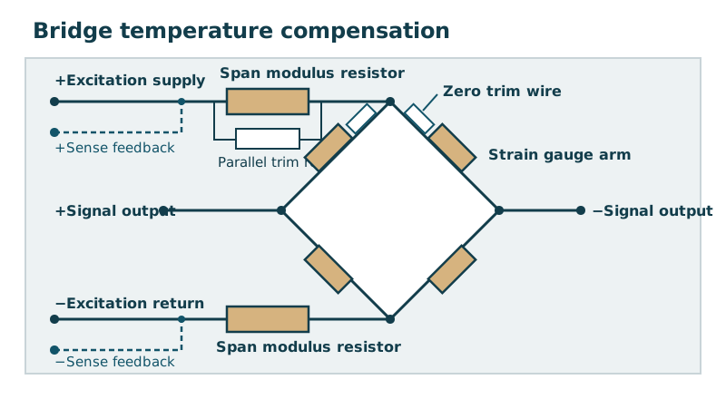
Zero drift is the change in zero load output of the load cell, expressed as a percentage of the rated load output per °C, and is compensated by adding a small amount of temperature sensitive resistance wire to the appropriate arm of the bridge circuit. Zero drift error, expressed as a force, is independent of applied load so its effect is worse when measuring forces that are only a small percentage of the rated load; the zero error can be removed if a zero load output reading is taken at the same operating temperature as the required load output reading. Span drift is the change in the output for an applied load, expressed as a percentage of the applied load output per °C; Young’s modulus decreases with rising temperature, causing an increase in the load cell output for an applied load.
LAUMAS defines rated output, expressed in mV/V, as the output value in mV that the load cell returns when the maximum load is applied, divided by the power supply voltage in V. In LAUMAS’s example, if a load cell has a full scale equal to 1000 kg and the effect of temperature on its full scale is 0,005% FS/°C, for each change in °C the reading can vary by at most 0,05 kg; if the temperature varies by 10°C (for example from 20°C to 30°C), the reading will vary by at most 0,05 x 10, that is 0,5 kg. In acam White Paper WP002, uncompensated load cell span error (gain drift) is typically in the range of 300 to 600 ppm/K; in its example, an uncompensated load cell of 10,000 g capacity with a gain drift of 500 ppm/K will drift 150 g over a temperature range of 30 K (a 1.5 % sensitivity change), whereas only 0.05 % gain drift is allowed for a 3,000 divisions weigh scale according to OIML.
| Metrological Parameter | Grounded OIML and Manufacturer Requirement |
|---|---|
| Combined error envelope | The Table 4 limits of error include errors due to non-linearity, hysteresis and temperature effect on sensitivity over certain temperature ranges specified in 5.6.1.1 and 5.6.1.2, while further errors are treated separately. |
| Minimum dead load output variation | Under Clause 5.6.1.3, the minimum dead load output over the temperature range specified in 5.6.1.1 or 5.6.1.2 shall not vary by an amount greater than the apportioning factor pLC times vmin for any change in ambient temperature of 2 °C for class A or 5 °C for classes B, C and D. |
| Error apportioning factor | The apportioning factor pLC shall be chosen and declared by the manufacturer in the range of 0.3 to 0.8, and if pLC is not specified on the certificate then the value 0.7 shall be assumed. |
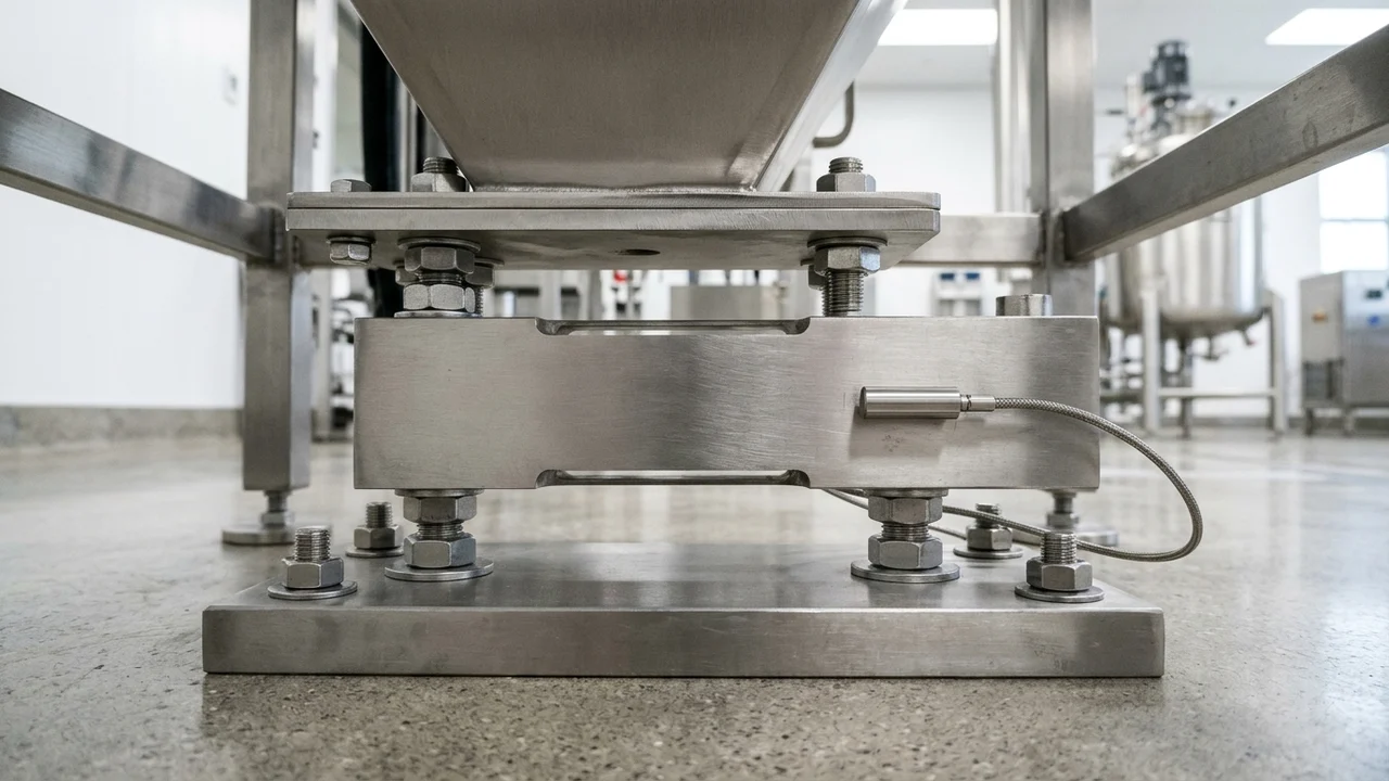
Trace how passive and active compensation networks trim bridge drift
Under Clause 3.1.3.1, an analogue-passive load cell may utilise passive electronics (e.g. strain gauges) and passive temperature compensation elements. Under Clause 3.1.3.2, an analogue-active load cell also utilises active electronics, which may be used for active temperature compensation. Under Clause 5.7.2.1, during the designed warm-up time of an analogue-active load cell there shall be no transmission of measurement results.
A full-bridge four-active-element strain-gauge configuration doubles bending-strain measurement sensitivity compared with a half-bridge implementation. In the OpenSEO Library capture of Test & Measurement Tips Part 2, a Wheatstone bridge can include an active strain gauge and a dummy strain gauge for temperature compensation mounted perpendicular to the direction of tension so its resistance is relatively unaffected by mechanical strain. For Wheatstone bridge passive temperature compensation to work, all gauges must be from the same foil lot, bonded to the same material, and exposed to the same temperature environment. Common Vishay STC codes match specific substrate approximate CTEs (in ppm/°C): STC 06 for ferritic/carbon steel and cast iron (~11.5 ppm/°C), STC 09 for 304 SS austenitic stainless steel (~16.7 ppm/°C), STC 13 for aluminum alloys 2024-T4 and 7075-T6 (~23.2 ppm/°C), and STC 05 for titanium and 410 stainless (~9.2 ppm/°C).
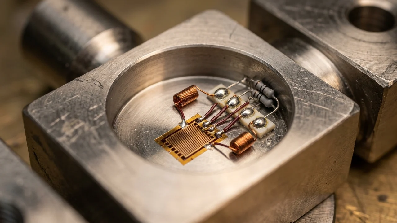
In acam White Paper WP002, the strain gage resistors RSG1 to RSG4 have a typical resistance variation of 0.2 % at full load, and although made of a temperature-stable alloy (e.g. Ni-Cr), they change resistance slightly over temperature in the range of < 5 ppm/K. In acam White Paper WP002, a drift mismatch of 0.5 ppm/K among the 4 strain gage resistors produces an offset drift of 2.5 µV/K at 5V bridge voltage (5 times higher than the limit given by the 3,000 division OIML specification), whereas a good load cell has approximately 100 nV/K (0.02 ppm/K mismatch) and requires adjustment of every single load cell in a temperature drift run using ROff1 and ROff2.
For standard temperature range load cells, Novatech compensates span drift using proprietary nickel or balco modulus compensation resistors in series with the excitation supply; because both the load cell span drift and resistor temperature characteristics are non-linear, compensation is not perfect, with good results over a range of -10°C to 50°C. Span drift error, expressed as a force, is dependent on the applied load, and the non-linearity of standard nickel or balco foil resistors increases at temperatures above 100°C while standard foil resistors are not suitable for use above 200°C. In acam White Paper WP002, the temperature-dependent Rspan resistor value is always chosen too high (overcompensation) so that it can be reduced afterward by paralleling standard adjustment resistors (RSAdj1 and RSAdj2) in the connection field, which also counteracts the load cell’s nonlinearity over temperature. In acam White Paper WP002, an unadjusted offset voltage at zero load is affected by the Rspan resistors: at 5 V excitation voltage, an unadjusted zero offset voltage of 0.4 mV/V (2 mV) with a Ubr variation due to Rspan of 1.5 % over 30 K results in an offset drift of 30 µV over 30 K (1000 nV/K), compared with approx. 100 nV/K for a good C3 load cell.
Check the compensated temperature range against the operating range
Under Clause 5.6.1.1, excluding temperature effects on minimum dead load output, the load cell shall perform within the limits of error in 5.3.2 over the temperature range of – 10 °C to + 40 °C, unless otherwise specified as in 5.6.1.2. Under Clause 5.6.1.2, when particular limits of working temperature are specified, the span of these ranges shall be at least 5 °C for class A, 15 °C for class B, and 30 °C for classes C and D. Under Clause 6.2.4.3, the special limits of working temperature (as referred to in 5.6.1.2) shall be specified in degrees Celsius (°C) when the load cell cannot perform within the limits of error in 5.3 to 5.6 over the temperature range specified in 5.6.1.1. LAUMAS defines the thermal compensation range (standard between -10°C and +40°C) as the temperature range within which the load cell can work observing the stated temperature errors on zero and full scale, whereas the working temperature range is the range within which the load cell can work without breaking, but in which data-sheet performance is no longer guaranteed.
Variations in temperature distribution over the load cell body can cause a zero drift greater than the data-sheet specification. If a load cell is constrained by an external structure, a real load change may occur due to differential expansion. Tacuna Systems states that high-strength aluminum (e.g., 2024, 7075) has a thermal conductivity four times higher than that of steel, allowing it to equalize temperature changes rapidly and prevent internal hot/cold spots that cause severe zero drift, while specialized outdoor load cells can have compensated temperature ratings as low as −20°C or −30°C.

| Load Cell Family | Published Temperature Coefficients, Resistances, and Temperature Windows |
|---|---|
| Alloy steel bending and shear beam | For the LAUMAS FTK load cell (AISI 4340 nickel plated steel), the rated output is 2 mV/V ±0.1%, temperature effect on zero is 0.002% °C, temperature effect on span is 0.0012% °C, compensated temperature range is -10 °C / +40 °C, and operating temperature range is -20 °C / +70 °C. |
| Alloy steel beam impedance and cable | For the LAUMAS FTK load cell, input resistance is 400 Ω ±10, output resistance is 352 Ω ±2, zero balance is ±2%, creep at nominal load in 30 minutes is 0.03%, max supply voltage without damage is 15 V, and the 6-core cable is 6m long (6 x 0.24 mm 2). |
| Stainless steel bending and shear beam | For the LAUMAS FTP load cell (AISI 420 stainless steel), the rated output is 2 mV/V ±0.4%, max supply voltage without damage is 15 V, temperature effect on zero is 0.002% °C, temperature effect on span is 0.0012% °C, compensated temperature range is -10 °C / +40 °C, and operating temperature range is -20 °C / +70 °C. |
| Stainless steel beam impedance by capacity | For the LAUMAS FTP load cell, input resistance is 385 Ω ±10 (for 75 to 2000 kg capacities) and 400 Ω ±15 (for 3000 to 10000 kg capacities), while output resistance is 350 Ω ±3 (for 75 to 2000 kg) and 350 Ω ±5 (for 3000 to 10000 kg). |
| Low-profile compression load cell | For the LAUMAS CBL compression load cell (17-4 PH stainless steel), rated output is 2 mV/V ±0.1%, input and output resistance are both 700 Ω ±10, temperature effect on zero is 0.005% °C, temperature effect on span is 0.003% °C, temperature range OIML R60 is -10 °C / +40 °C, compensated temperature range is -20 °C / +70 °C, operating temperature range is -30 °C / +90 °C, and max supply voltage without damage is 15 V. |
| Weigh module minimum dead load output | In the METTLER TOLEDO SWC415 PinMount datasheet, the SLC611 load cell has a temperature effect on minimum dead load output (%R.C./°C) of ≤ 0.0018 (0.0010 /°F), whereas the 0782 load cell has a temperature effect on minimum dead load output (%R.C./°C) of ≤ 0.0021 (0.0011 /°F). |
| Weigh module sensitivity and ranges | In the METTLER TOLEDO SWC415 PinMount datasheet, both the SLC611 and 0782 load cells have a rated output of 2 ± 0.1 % mV/V @R.C., combined error ≤ 0.018 %R.C., temperature effect on sensitivity ≤ 0.001 %A.L./°C (0.0006 %A.L./°F), compensated temperature range -10 ~ +40 °C (-14 ~ +104 °F), operating temperature range -40 ~ +65 °C (-40 ~ +149 °F), and safe storage range -40 ~ +80 °C (-40 ~ +176 °F). |
| Packaging machine load cell parameters | In the OpenSEO Library capture of Fill Package’s packaging load cell guide, typical packaging load cell parameters include class c2, c3, c4, and c5, combined error 0.03 fs, 30 min creep 0.02, temperature effect 0.002 per 10 c, excitation 15 vdc to 18, and operating temperature 70. |
Control excitation self-heating and four-wire versus six-wire cable drift
Increasing the excitation voltage increases sensitivity and signal-to-noise ratio, but increases power dissipation in each strain-gauge element with the square of the excitation voltage, making the gauge susceptible to self-heating and thermal error relative to the test specimen; consequently, excitation voltage should remain as low as possible while maintaining an adequate signal-to-noise ratio. Self-heating from excitation voltage raises the strain gauge temperature above ambient, distorting STC behavior and increasing zero-load instability, so excitation should be sized to grid area and substrate heat-sink capacity. LAUMAS states that weight indicators and weight transmitters usually have a standard power supply value of 5VDC or 10VDC, and any non-standard power supply devices must observe the maximum power supply voltage stated on the data sheet so as not to damage the load cell. In the METTLER TOLEDO SWC415 PinMount datasheet, both SLC611 and 0782 load cells have a recommended excitation voltage of 5 ~ 15 V AC/DC and a maximum excitation voltage of 20 V AC/DC; excitation terminal resistance is 1150 ± 50 Ω for SLC611 (output 1000 ± 2 Ω) and 1150 ± 25 Ω for 0782 (output 1000 ± 3 Ω), and the 0782 cable includes + Sense and - Sense cores unlike the SLC611 cable.
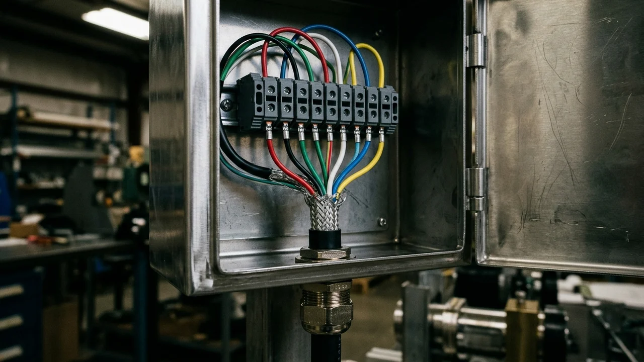
Copper lead wires have a Temperature Coefficient of Resistance (TCR) of 3,930 ppm/°C (per NIST Handbook 100), roughly 100 to 200 times higher than typical gauge foil alloys such as constantan (~±20–30 ppm/°C). LAUMAS states that in 6-core cables, 2 reference wires (Sense + and Sense-) allow load cells to offset any change in voltage drop on the cables due to temperature or cable length, whereas 4-wire load cells are calibrated and thermally compensated in relation to their standard supplied cable length, so their cable length should not be altered. In Section 6.2 of the HBK C16 Mounting Instructions, connecting the load cell to an amplifier using the four-wire technique (connecting BU/blue with GN/green and BK/black with GR/grey) causes deviations to the sensitivity and the temperature coefficient of sensitivity. In Section 6.3 of the HBK C16 Mounting Instructions, when extending a load cell cable with the four-wire technique, the sensitivity deviation can be rectified by adjustment, but temperature effects are only compensated when operating with the six-wire technique.
Continue with the Wheatstone bridge and sense wiring guide, the load cell amplifier and fieldbus guide, or the load cell mounting and side-load guide.
Record temperature coefficients and operating ranges before specifying a cell
Prepare these datasheet and site records before approving a load cell or diagnosing thermal drift:
- The minimum and maximum ambient and process temperatures at the mounting point, compared against both the compensated temperature range and the operating temperature range.
- The datasheet temperature coefficient on minimum dead load output and temperature coefficient on sensitivity, together with the required minimum verification interval and dead-load-to-live-load ratio.
- The transmitter excitation voltage, bridge input resistance, and whether six-wire sense feedback is terminated at the load cell or junction box.
Continue with the load cells and controls collection or review packaging load cell installation.
Sources
- International Organization of Legal Metrology, Metrological Regulation for Load Cells
- Novatech Measurements Ltd, Load Cell Temperature Effects Engineering Sheet
- PMT and acam-messelectronic, Temperature Compensation of Load Cells White Paper
- LAUMAS Elettronica, Load Cell Technical Features Guide and FTK, FTP, and CBL Data Sheets
- METTLER TOLEDO, PinMount Weigh Module Data Sheet
- HBK, Self-Restoring Pendulum Load Cells Mounting Instructions
- SensorData Technologies, Temperature Compensated Strain Gauge Guide
- Test & Measurement Tips, Defining and Measuring Strain Series
- Massload Technologies, Load Cell Temperature Compensation Guide
- Tacuna Systems, Winter Temperatures Effects on Load Cells Guide
- OpenSEO Library, High-Precision Load Cell for Packaging Machinery Reference