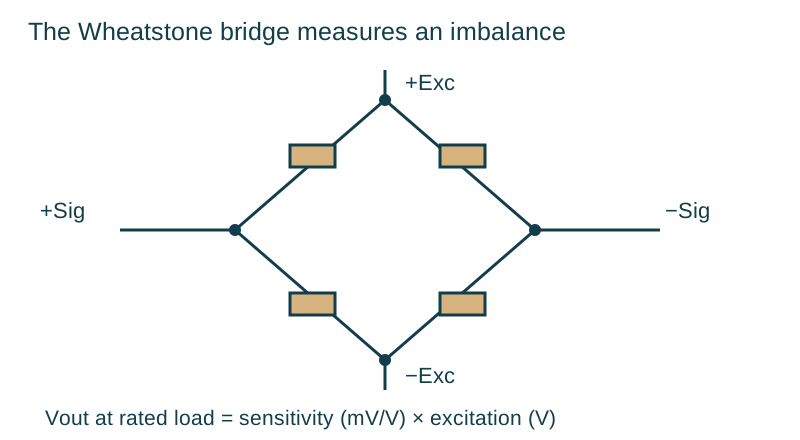
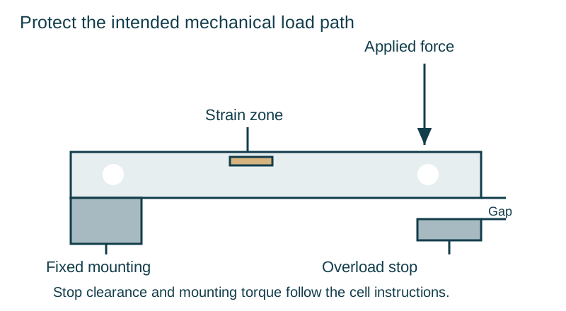
In this guide
Select a load cell amplifier or weight transmitter around the complete control loop. The important comparison is how a bridge change becomes a reliable PLC value and then a filling action. ADC bit depth, conversion rate, digital filtering, bus update, PLC scan and actuator response contribute different parts of that result.
Compare the signal chains
An analog conditioner delivers a signal such as 4–20 mA or 0–10 V to a PLC analog input. The PLC converts and scales that signal. A digital weight transmitter converts the bridge signal internally and sends weight data through its communication interface, often with status and diagnostic information.
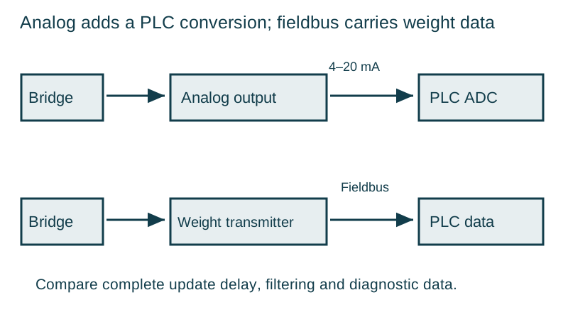
The analog path requires consistent zero and span at both the conditioner and PLC. The digital path requires agreement on units, scaling, data format, status bits and update behaviour. Neither interface removes the need for correct grounding, mechanical installation or validation of the measured weight.
Use published hardware as a bounded comparison
LAUMAS documents the following features for two specific offerings. Confirm the ordered option and current technical documents before using the values in a design.
| Published feature | LAUMAS TLC analog transmitter | LAUMAS TLB4 PROFINET IO |
|---|---|---|
| Physical format | Board version: 45 × 26 × 11 mm | DIN-rail unit: 26 × 115 × 120 mm |
| Load-cell arrangement | Up to four cells in parallel | Four independent reading channels |
| Output/interface | 4–20 mA or 0–10 VDC | Two PROFINET IO ports; RS485 with Modbus RTU/Laumas ASCII |
| Adjustment/control | Rated-output switches; 12-turn zero and full-scale potentiometers | Display and keys for calibration; individual monitoring and digital equalization |
| Published conversion specification | See the TLC technical documentation for the chosen version | Four-channel 24-bit A/D converter; listed conversion frequency 4.8 kHz |
These figures come from LAUMAS’s New TLC analog weight transmitter announcement and TLB4 PROFINET IO product page. The 4.8 kHz conversion specification is not the PLC’s guaranteed weight-update rate. Likewise, a 24-bit converter does not establish the usable resolution or dynamic accuracy of the installed weighing system.
Read: LAUMAS — New TLC analog weight transmitter.
Read: LAUMAS — TLB4 PROFINET IO.
Budget the delay through the whole loop
A practical response budget includes sensor and mechanical settling, conversion and filtering, data transfer, PLC processing, output actuation and product travel. Determine which terms overlap in the actual architecture and which add sequentially. Test the total with the process running.
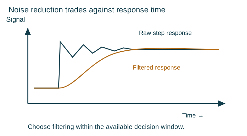
Digital filters trade noise reduction against response. A heavily smoothed weight can look stable while lagging a fast fill. Choose filtering against the permitted cutoff error and actual disturbance, rather than setting it to the quietest possible display.
CANopen, EtherNet/IP and Modbus describe different communication choices; a product family offering several variants does not mean one unit supports all of them. Check the exact interface module, mapping file or register map, signed value format, scale factor, watchdog and loss-of-communication response. Decide whether cutoff executes locally in the weight controller or through the PLC.
Coordinate coarse feed, fine feed and in-flight material
A filling sequence often reduces delivery near target and stops before the measured weight reaches the final target. The remaining material arrives during actuator closing and transit. In a simple steady-flow approximation, in-flight mass ≈ mass flow × effective delay; validate the relationship when flow, head pressure or material condition changes.
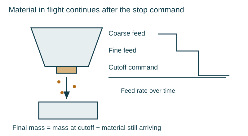
Use finished-fill results to assess an authorized adaptive correction. Limit the correction so a blocked chute, empty hopper or noisy sensor cannot drive large parameter changes. Keep recipe-specific settings and alarm conditions with the acceptance record.
Address interference at its source
Variable-frequency drives, motor cables and switching devices can couple interference into a small bridge signal. Follow the equipment instructions for cable routing, shields, protective earth and separation. A current loop can be useful for transmission, but loop integrity, input range, common-mode conditions and fault detection still need attention.
For digital systems, inspect both the analog bridge connection and the network. Data that arrives reliably can still contain a disturbed measurement. Independent-channel diagnostics, where available, help separate a cell or wiring problem from a common load or process disturbance.
Prove the interface under real faults
Verify zero and span, increasing and decreasing load, update behaviour, power recovery and communication loss. For filling, include the fastest required cycle, hopper-level changes and the product state that produces the longest tail. Confirm that stale, invalid or overrange data causes the defined safe response rather than continuing as a valid weight.
Use the bridge wiring guide when the raw sensor signal must be checked before changing PLC scaling or filters.
Continue with the load cells and controls collection.