In this guide
A loss-in-weight feeder measures the decrease in the mass of its hopper and feeding assembly over time. The controller compares that mass-flow estimate with a setpoint and adjusts the delivery mechanism. The system must distinguish product leaving the feeder from forces introduced by refill, pressure, hoses and nearby equipment.
Define the weighing boundary
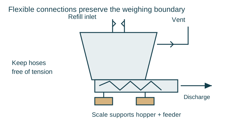
The hopper, feeder and relevant drive components form the weighed assembly. The supporting scale measures their combined load. Inlet, outlet, vent and electrical connections must accommodate the intended movement without creating an uncontrolled parallel force path.
Thayer describes its loss-in-weight systems as a volumetric feeding mechanism mounted on a scale with closed-loop correction of feeder output. The screw or vibratory mechanism still has to handle the material consistently. Weight feedback cannot deliver powder through a bridge that has stopped material reaching the screw.
Calculate the loss rate and close the loop
During normal discharge without refill, mass-flow rate q = −dM/dt. Over a finite measurement interval, the estimate is the decrease in measured mass divided by elapsed time. Use consistent mass and time units and confirm whether the displayed rate is instantaneous, filtered or averaged.
A PID controller can use the error between target flow and measured flow: the proportional term responds to current error, the integral term accumulates persistent error, and the derivative term responds to its rate of change. Actual feeder controllers may implement specialized estimation, compensation and tuning instead of exposing a simple generic PID loop.
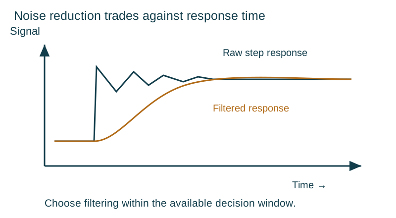
Tune only through the controller’s authorized procedure. An aggressive response can amplify measurement disturbance, while excessive smoothing can hide real flow changes. Set limits and anti-windup behaviour appropriate to empty-hopper, refill and actuator saturation conditions.
Treat refill as a distinct measurement state
During refill, incoming material increases the scale reading while the feeder may continue discharging. The ordinary falling-weight calculation can no longer isolate outgoing flow. The controller uses its configured refill strategy, such as stored feed behaviour or volumetric operation, until the weight signal becomes suitable for gravimetric control again.
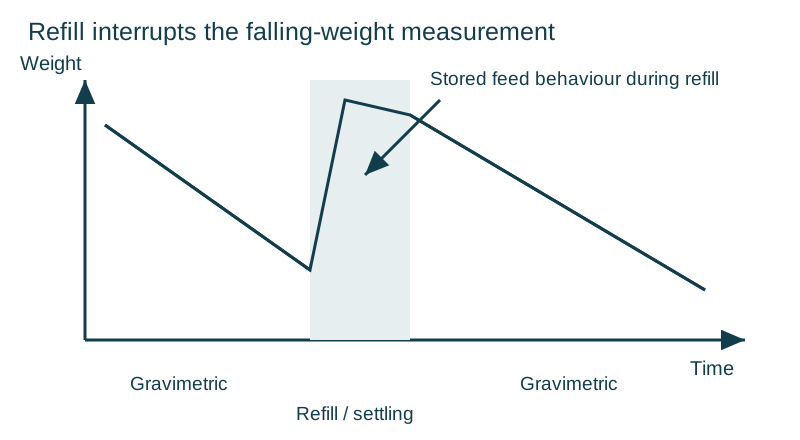
Coperion’s technical paper on feeder trending describes maintaining discharge during refill and investigating the weight disturbance that follows it. Refill hardware, material transit and venting influence the return to stable measurement. Match the refill device and hopper size to the manufacturer’s application design rather than copying a timing value from another installation.
Record refill start and stop, hopper weight, feeder speed, calculated flow and recovery status on one timeline. This exposes late material arrival, long settling, valve leakage or a refill rate that overwhelms the hopper’s venting arrangement.
Read: Coperion K-Tron — Using trending capabilities to troubleshoot continuous feeder performance problems.
Control vent pressure and flexible-connection forces
Air must move as powder enters or leaves the hopper. Coperion explains that a clogged vent or overly aggressive extraction can produce pressure changes and forces through flexible connections. A hose can be flexible by construction and still exert a significant force when stretched, misaligned, inflated or pulled by suction.
Inspect vent filters, hose routing, supports and connection alignment. Keep upstream and downstream equipment mechanically isolated as the design requires. Evaluate changes after cleaning or maintenance: a hose reinstalled under tension can change the scale reading even though the electrical system is unchanged.
Interpret trends before changing tuning
| Trend pattern | Investigation priority | Evidence to retain |
|---|---|---|
| Flow falls while drive demand rises | Bridging, starvation or delivery restriction | Hopper weight, speed and material condition |
| Weight changes with extraction state | Pressure or connection force | Vent condition and extraction events |
| Disturbance follows every refill | Refill impact, trailing flow or venting | Refill timing and recovery duration |
| Noise tracks nearby machinery | Vibration or mechanical contact | Synchronized machine events |
| Stable speed but changing delivered mass | Density, screw filling or calibration | Timed collection and reference mass |
Verify both steady flow and transitions
Use the manufacturer’s safe collection and reference-weighing procedure to check delivered mass over the specified interval. Include normal operation, refill, startup and the required operating range. Reconcile the time base and units between the controller and reference measurement.
For powders, address dust containment, cleaning and applicable explosion-protection requirements as part of the complete installation. Isolate the equipment before clearing blockages or inspecting moving parts. Keep accepted settings and the tested material condition with the commissioning record.
The volumetric versus gravimetric guide places loss-in-weight control alongside package-filling alternatives.
Continue with the packaging weighing systems collection.